Efficient
100% efficient integration time


Pioneering GPR Technology
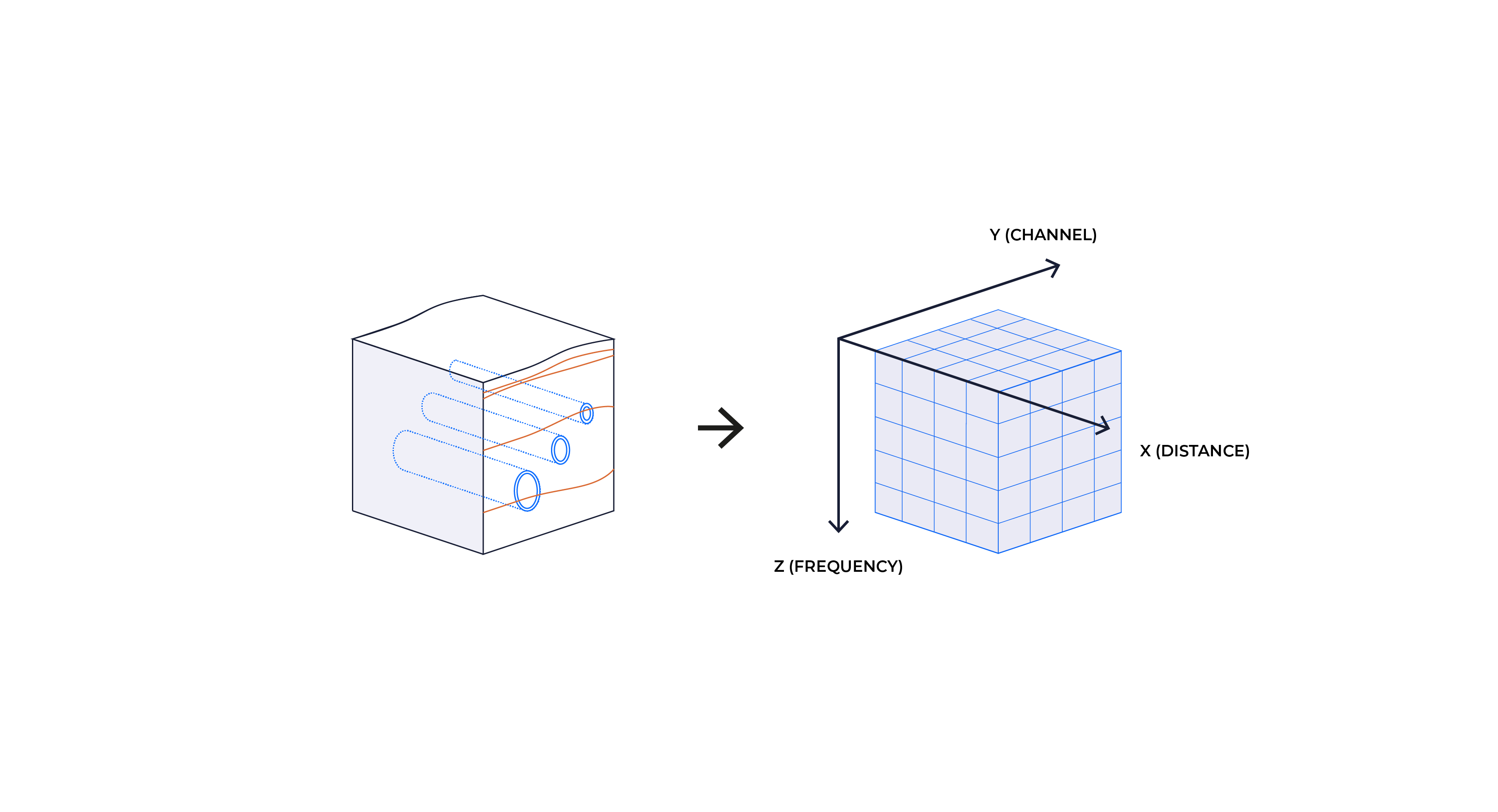
Our system is designed for high-resolution and 3-dimensional subsurface mapping thanks to the use of our antenna arrays together with Examiner ™. The system uses a patented and unique step-frequency radar technology, which is a vital part of evolving the rest of the GPR industry.
100% efficient integration time
Adjustable survey parameters including trigger spacing, time window, dwell time and more
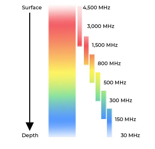
Continuous frequency coverage from the 30 MHz range up to 4.5 GHz
The raw measurement data can be stored as frequency domain data. Allowing the user to reprocess data with different frequency weighting to enhance the features of interest
It’s possible to perform frequency-domain absorption analysis to study phenomena related to concrete delamination
The frequency-domain data is perfectly suited for fast FK-migration for image focusing
The step-frequency signal is a low peak-power signal with a low probability of interference with other radio systems. The Kontur step-frequency system will only transmit a burst of energy when performing a scan
The system is self-calibrating with no time-drift removing the need for warm-up time or re-calibration in the field

Step-frequency is a radar waveform consisting of a series of sine waves with linearly increasing frequency. The radar measures the phase and amplitude on each frequency and uses an inverse Fourier transform of this data to build a time-domain profile (A-scan). Thus, the step-frequency radar collects data in the frequency domain and converts the data to time-domain data through computer processing. The step-frequency waveform gives the optimum source signature with a uniform frequency spectrum. The computer control allows the user to set the dwell time on each frequency as well as the start and stop frequencies.

Impulse-based radars transmit very short pulses (impulses) with a fixed pulse repetition rate (PRF) and use stroboscopic sampling to build the time domain trace from several subsequent pulses. Hence, the impulse-based radar data is the direct reading of the time-domain reflection from the underground. The step-frequency radar data can either be stored as frequency domain data or as time-domain data after inverse Fourier transform. The time-domain data from a step-frequency radar are equivalent to time-domain data from an impulse-based radar. However, the frequency data allows a much wider range of frequency-domain processing possibilities.
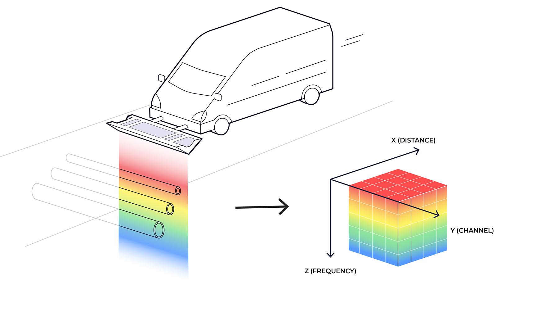
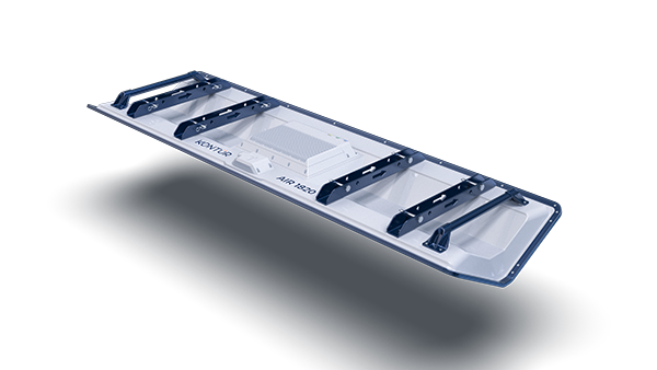
In contrast to traditional octave-band GPR antennas, our ultra-wideband bow-tie monopoles have continuous frequency coverage from the 30 MHz range up to 4.5 GHz. This allows us to collect the full frequency response from the subsurface, giving us the optimal resolution for any given depth point, and a true 3-dimensional data cube.
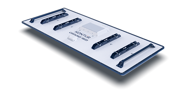
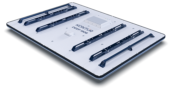
All of our antennas are multi-channel arrays, which allows for fast data acquisition over large collection areas.
A similar survey using traditional single frequency antennas would require multiple antennas, for example a 200 MHz, a 400 MHz, an 800 MHz and a 1600 MHz antenna, which increase time, cost and complexity for the survey.
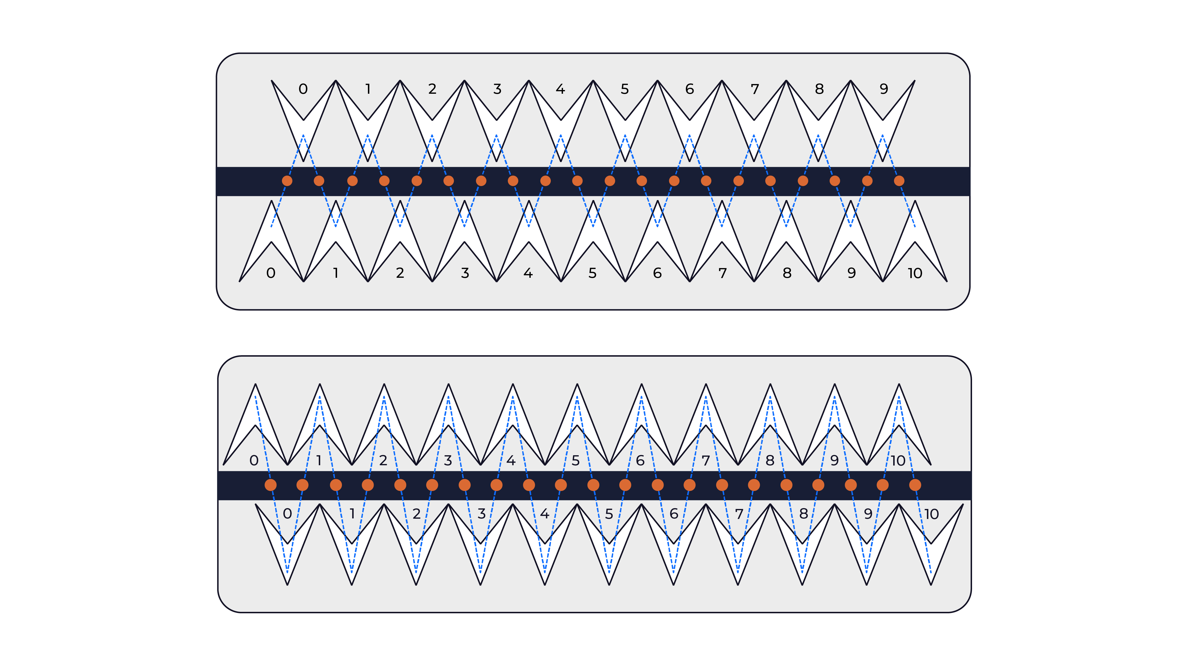
The sensor elements are arranged in a linear array where the transmitting and receiving sensors are displaced to each other. During the survey, the radar combines the transmit/receive antennas sequentially to obtain a number of profiles (or channels).
The multi-offset recording allows the user to set up sensor scanning sequences with independent transmitter and receiver antenna locations.
With the multi-offset feature, the system offers a higher degree of freedom to build more advanced scan patterns. For instance, it’s possible to transmit at Antenna #1 and receive at Antenna #8, (i.e. with an offset distance along the cross-line direction).
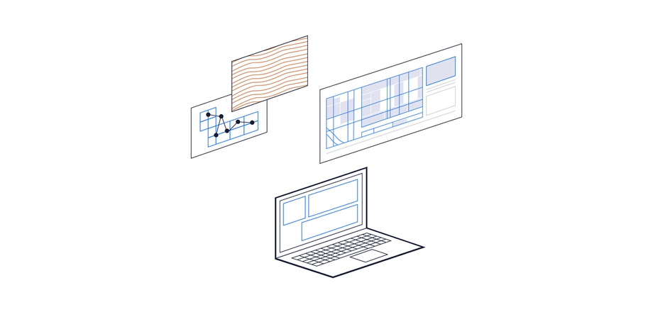
Our AIR, GROUND, and DEEP sensors are controlled by, and write data directly to, the operator’s laptop. The operator can optimize the collection settings for the application and ground conditions to maximize the collection data set.
There is a real time data view in the Collection client software that allows the operator to ensure that good data is being collected, and add markers to match surface landmarks during the collection.
The incoming data can be automatically processed during collection, allowing for viewing the processed data during collection in our Examiner processing software.